AI Servers / The physical network
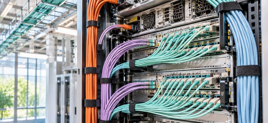
AI rack cabling can involve hundreds of physical connections—but none of those cables is supposed to go nowhere. Behind the neatly closed doors of an AI computing rack is a carefully planned system of power leads, high-speed network links, management connections and pathways to equipment outside the cabinet.
The cable count depends on the hardware. A rack containing several independent GPU servers is wired differently from a rack-scale platform whose accelerator fabric uses dedicated rear interconnect assemblies. Still, the practical challenge is the same: every connection needs a destination, safe routing and a way to be serviced without disturbing its neighbors.
The short answer: data cables travel toward switches or patch panels; power leads connect to rack distribution and upstream protected power; management ports go to a separate service network. The visible bundle is the physical map of how the AI system communicates and stays powered.
Why one rack can accumulate so many cables
A GPU-equipped server does not work alone. Its network adapters connect it to other compute nodes, storage systems and management tools. The server also needs power. A rack full of independent machines multiplies those connections before cables to switches, monitoring devices and rack power distribution are counted.
For a concrete example, NVIDIA’s DGX H100/H200 system documentation describes separate high-speed networking, storage/in-band networking and management interfaces; the system ships with six qualified locking power cords. That is a system-specific fact, not a formula for every AI rack.
Rack-scale systems can change the arrangement dramatically. In NVIDIA’s Grace Blackwell rack-scale networking description, dedicated rear cabling cartridges connect compute and NVLink switch trays, while Ethernet and other external network roles remain distinct. So a large rack might contain many engineered interconnects without resembling a simple bundle of ordinary Ethernet patch leads.
High-speed Ethernet or InfiniBand links carry distributed training and node-to-node traffic, depending on the platform.
Separate or shared data links move datasets, checkpoints and model artifacts between compute and storage.
Qualified power cords feed approved rack PDUs or distribution equipment; A and B paths may support designed redundancy.
Service ports allow monitoring and maintenance, often through a logically or physically separate management network.
First stop: the back of the server
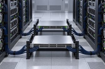
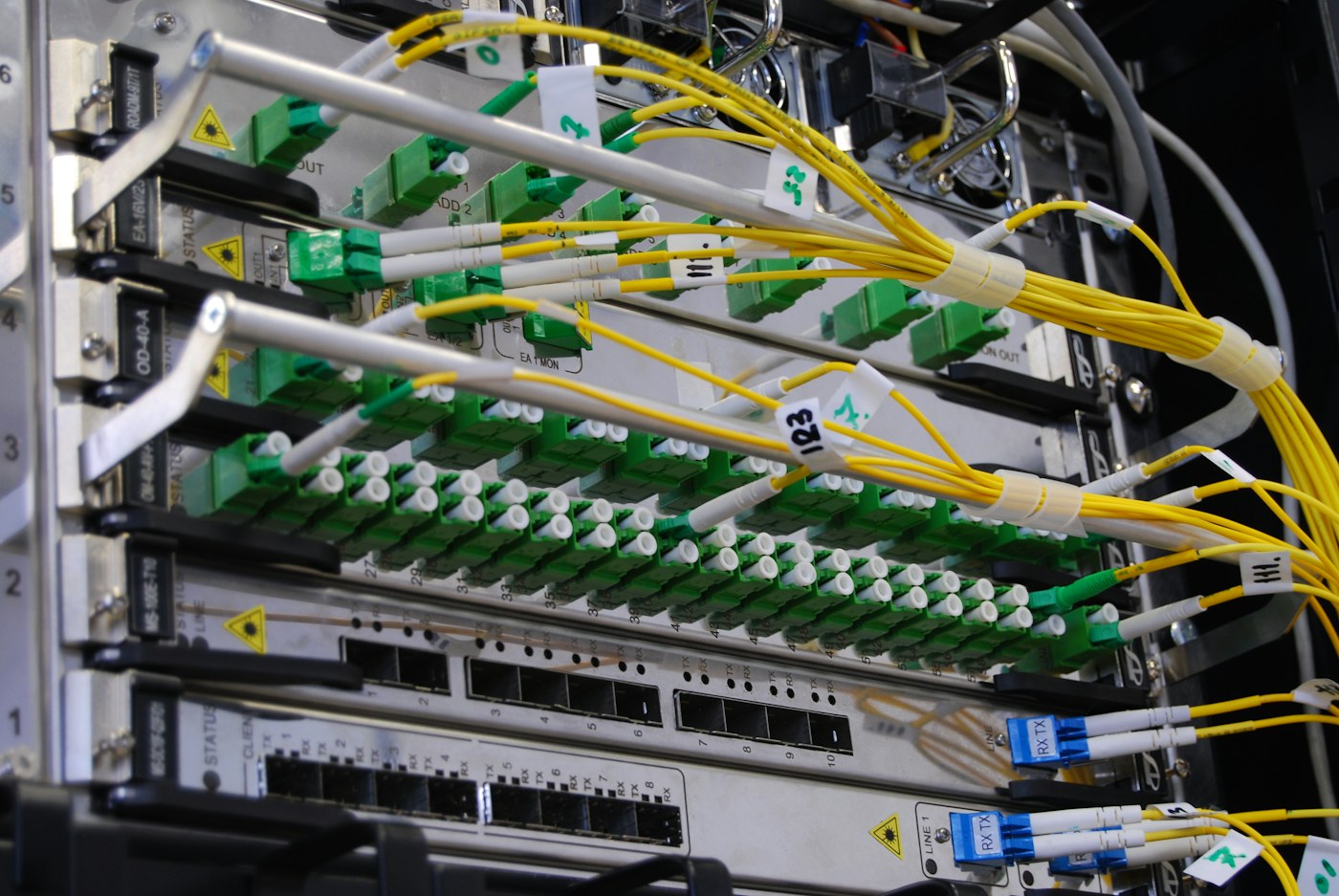
In many traditional rack deployments, cables leave network adapters or management ports on the back of a server. They enter horizontal or vertical cable managers where the bundle is supported instead of hanging from connectors. Short patch leads may reach a top-of-rack switch. Longer links may run to an end-of-row switch, structured patching or another rack.
The route matters as much as the destination. A heavy cable hanging from an optical transceiver can place stress on the port. Tight bends can damage fiber or degrade optical performance. Crowded bundles can make it difficult to remove a server or inspect a failed connector without disturbing several healthy connections.
Where the cables go after leaving the cabinet
Data cabling can pass through overhead ladder racks or, in some facilities, underfloor pathways. It may reach fiber distribution frames, spine or leaf switches, adjacent cabinets, storage arrays or network aggregation points. Designers choose pathways for physical protection, separation, airflow and future maintenance—not simply for the shortest possible distance.
Power wiring follows a different route. Equipment cords terminate on approved rack power distribution units and connect into the facility’s electrical architecture. A and B power feeds, if provided, are assigned to the intended redundant paths. Running both through a common unsupported dependency would undermine the purpose of redundancy.
Liquid-cooled racks introduce another category: fluid hoses and manifolds. They can visually resemble large cable runs, but they are not data cables. Their safety, service clearances and leak-management requirements must be planned separately. Our earlier explainer about how a 135 kW AI rack rejects heat explores that neighboring physical system.
Why neat cable management is a reliability issue
Optical performance. Fibers have minimum bend radii and pulling limits set by the cable and connector manufacturer. Routing guides and radius-controlled supports reduce stress. Cisco’s physical infrastructure guidance discusses supporting fiber vertically and horizontally and avoiding damaging bends in rack environments.
Service access. A GPU server should be removable according to the approved maintenance procedure without disconnecting the wrong switch uplink or tugging on another machine. Engineers leave the appropriate service allowance while avoiding huge uncontrolled loops of spare cable.
Fault isolation. A loose connection must be traceable from one port to its exact peer. Labels, mapping databases and change records matter as much as cable colors. Two identical-looking optics can serve different fabrics.
Air and temperature. Dense cabling can obstruct airflow if routes cross equipment intakes or exhausts. This is especially consequential when high-power systems already depend on carefully designed thermal paths.
Redundant paths. Cables that appear separate in a diagram can meet at the same tray, patch panel or switch. Redundancy requires a careful look at shared physical failure points. IL.DIGITAL’s analysis of AI-cluster switch failures explains why the surviving network path matters to the workload.
A maintenance engineer’s checklist
- Know both endpoints. Every lead should map to a specific device, port, fabric and purpose.
- Separate functions. Power, data, management and liquid-cooling routes need their intended clearances and controls.
- Respect cable specifications. Use approved connectors, lengths, bend allowances and strain relief.
- Plan for replacement. Leave access to server trays, power shelves and hot-swappable parts where supported.
- Test the real failure path. Verify that an alternate network or power route works after a single component is removed, if the architecture promises one.
- Document changes. A physically neat rack can become operationally opaque when labels and topology records are stale.
Questions people ask about AI rack cabling
Are all the cables connected to the GPUs?
No. Some connect host network adapters, system management interfaces, switches, storage systems and rack power equipment. Internal GPU interconnects can be board-level or specialized rack-scale fabric assemblies rather than individual external patch cables.
Why not use wireless networking inside the rack?
Current high-throughput AI fabrics rely on tightly specified wired links for predictable bandwidth, latency and signal integrity. Wireless would not be a drop-in substitute for the interconnects described in these server architectures.
Can everything go through one overhead tray?
Not automatically. Tray design, separation, weight, fire requirements, fiber support and service access are site-specific engineering questions. The relevant standards and manufacturer instructions govern the route.
From the outside, a rack can look like one metal cabinet with blinking lights. Inside, it is a junction of several carefully separated systems: compute, communication, storage, power and sometimes liquid cooling. This is why a network port can become the limiting resource before another GPU is installed—and why clean topology matters as much as a clean-looking bundle.
For a larger view of this trend, see IL.DIGITAL’s report on why AI network switches increasingly need dedicated cooling. The supporting network has become an engineering system in its own right.
Every cable is part of a contract: it carries a specific kind of traffic or power between two defined points. A reliable AI rack is not one with the fewest visible wires. It is one where the purpose, path and failure behavior of each connection are understood.