- AI rack cooling begins with the heat load
- Liquid cooling does not eliminate air cooling
- Follow the heat from a GPU to the outdoors
- How a liquid-cooled AI rack rejects heat
- How much liquid would have to circulate?
- Original calculation: three coolant scenarios
- The 10°C case, step by step
- The 10% air load is still a design problem
- Five questions to ask before installing a high-density rack
- Does liquid cooling make data centers water-free?
- Published specifications, transparent calculations, no fictional test bench
- Sources and further reading
- The heat is real. The water story depends on the last mile.
One cabinet. Seventy-two GPUs. A cooling system that has to move the equivalent of a small building’s heating load away from the electronics, minute after minute.
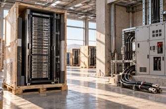
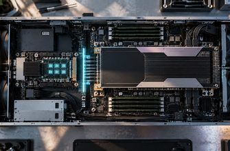
AI rack cooling becomes a very physical problem at 135 kilowatts. In Lenovo’s published GB300 NVL72 design, 72 Blackwell Ultra GPUs share a rack with Grace CPUs, network switching, power hardware and two different ways of removing heat. The manufacturer says roughly 90% of the rack’s heat is captured by liquid. The rest still reaches the room air.
That number is worth following. If most of the heat enters a coolant loop, where does the coolant take it? How fast must it move? And does circulating hundreds of liters per minute mean a data center is consuming that much fresh water?
We used Lenovo’s published rack figures, an openly stated heat-balance calculation, and cooling-system guidance from ASHRAE and the US Department of Energy to trace the answer. These are engineering estimates, not measurements from a rack operated by il.digital.
AI rack cooling begins with the heat load
Lenovo’s GB300 NVL72 product guide describes a 72-GPU, 36-CPU rack with a 135 kW thermal-design figure and peak power that can reach 155 kW depending on workload and electrical design conditions. It also specifies a hybrid cooling layout: the CPUs, GPUs, memory and NVSwitch hardware use liquid cooling, while items such as storage and some power and optical components still rely on moving air.
Nearly all of the electrical energy used by computing hardware ultimately becomes heat in the facility. A thermal-design rating is not a continuously measured power draw, but it is a useful reference load for understanding what a cooling plant must be built to handle.
Liquid cooling does not eliminate air cooling
Using the published approximate 90/10 split at the 135 kW reference point gives 13.5 kW still delivered to air. That is not a tiny residual to ignore. The room still needs an airflow plan, and the facility must reject that heat as well as the heat carried in liquid.
The values above mix a manufacturer specification with a clearly labeled calculation. The fractions are reference-design approximations, not a measured heat audit of a deployed rack.
Follow the heat from a GPU to the outdoors
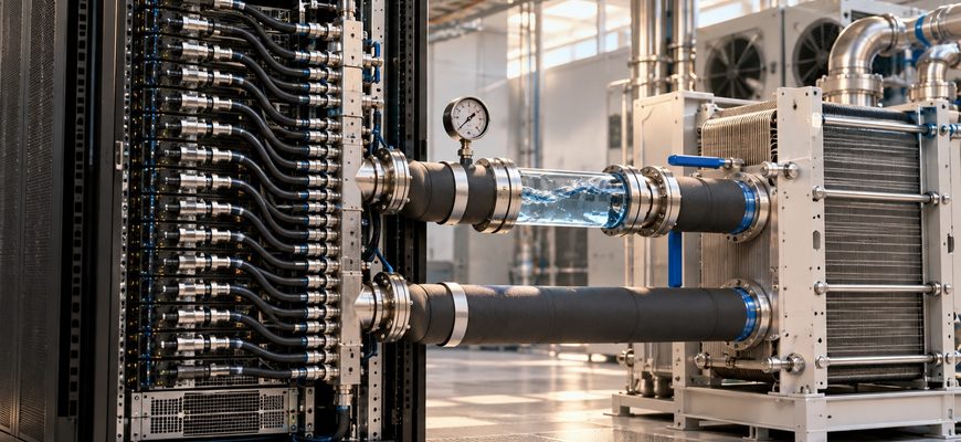
The liquid does not make heat vanish. Cold plates transfer energy from components into circulating coolant. That coolant travels through rack manifolds and hoses to a coolant distribution unit (CDU), where a heat exchanger can pass energy into a separate facility loop. Pumps, controls and sensors maintain the required conditions.
ASHRAE calls the equipment-side loop the technology cooling system. Keeping it distinct from the building-side loop allows engineers to manage fluid quality and temperatures without assuming that the liquid touching a cold plate is the same water used in a cooling tower.
How a liquid-cooled AI rack rejects heat
CUTAWAY / 01How much liquid would have to circulate?
Here is the part we can calculate from first principles. For a single-phase liquid loop at steady state, the heat carried by the fluid depends on mass flow, specific heat and the temperature rise between inlet and outlet:
Q = ṁ × cp × ΔT
Take the 121.5 kW liquid-side load derived above. For illustration, use water at roughly room-temperature properties: specific heat 4.18 kJ/(kg·°C) and density near 1 kg/L, consistent with the NIST liquid-water reference. Now change only one variable: how much warmer the coolant leaves the load than it arrived.
Original calculation: three coolant scenarios
TABLE 01| Coolant temperature rise | Illustrative flow | What changes |
|---|---|---|
| 5°C | ≈ 349 L/min | A small temperature rise needs more circulating liquid for the same heat removal. |
| 10°C | ≈ 174 L/min | Doubling the rise roughly halves the required flow in this simplified calculation. |
| 15°C | ≈ 116 L/min | A larger rise lowers theoretical flow but must remain within equipment thermal limits. |
How these flow values were calculated
Calculation: Flow [L/min] ≈ 121.5 [kJ/s] × 60 ÷ (4.18 [kJ/(kg·°C)] × ΔT [°C]). Results are rounded and assume water density of approximately 1 kg/L.
Limitations: These are illustrative circulation rates, not Lenovo’s specified operating flow. Real values depend on coolant mixture, inlet and return temperatures, actual captured heat, component limits, hydraulic design and measured workload.
The 10°C case, step by step
121.5 ÷ (4.18 × 10) = 2.91 kg/s. With the illustrative density approximation, that is about 2.91 liters each second. Multiply by 60 seconds and the loop circulates about 174 liters per minute.
At this reference load, the liquid side carries about 7.29 megajoules of heat energy per minute. The whole 135 kW rack corresponds to 8.1 megajoules per minute at the assumed load. Neither figure tells us the actual temperature of the chip.
Do not read 174 L/min as water consumption. It is a calculated circulation rate in a hypothetical single-phase loop. The same liquid can pass through the equipment again and again. Water consumption depends on how the facility ultimately rejects heat and on losses or makeup elsewhere in the system.
This is also why a pump flow specification alone cannot tell you a site’s water footprint. A cooling tower may evaporate water and require makeup. A dry cooler can reject heat to air without relying on the same evaporation mechanism. Both can be paired with recirculating equipment-side loops. The US Department of Energy describes these distinctions in its data-center water-efficiency guidance.
The 10% air load is still a design problem
At the same 135 kW reference point, the air side receives approximately 13.5 kW. In Lenovo’s configuration, air still cools items such as storage, optical modules and power-distribution components. Operators need the right inlet conditions, airflow paths and room cooling capacity even when cold plates capture most of the compute heat.
Nor can a facility designer assume that a large water-side temperature rise is always safe. The pump must overcome pressure losses, the cold plates must keep component temperatures within limits, and the CDU and building plant must remain effective as outdoor conditions change. One attractive result from a simple heat equation cannot replace a vendor thermal specification.
Five questions to ask before installing a high-density rack
For a facility engineer or anyone comparing AI infrastructure, the useful outcome is a cooling plan with explicit boundaries, not just a headline rack wattage.
- At what workload and power limit is the rack rated? Keep TDP, typical measured use and possible peak conditions separate.
- How much heat goes to liquid versus room air? Both paths require capacity; neither is optional simply because the other dominates.
- What coolant, inlet temperature, flow and pressure limits apply? Water, deionized water and glycol mixtures do not behave identically.
- Where does the CDU send the heat? Trace the facility loop to its actual final heat-rejection or heat-reuse equipment.
- What is monitored during a fault or warm day? Measure supply/return temperature, flow, pressure, leak detection and the remaining cooling margin under load.
These questions become more important as rack density rises. The Open Compute Project’s cold-plate work focuses on the very ordinary-looking components that make this possible: cold plates, connectors, manifolds, fluids and CDUs. Real deployability depends on those interfaces as much as on GPU specifications.
Does liquid cooling make data centers water-free?
No. It can make the chip-to-coolant path more effective, but it does not by itself specify the building’s water consumption. Cooling towers, dry coolers, evaporative assistance, chillers and reuse schemes make different trade-offs between water, electricity, ambient conditions and infrastructure cost.
That distinction also helps connect this story to the data center that warms a swimming pool in Exmouth. The unusual part of that project is not that computers produce heat. Every loaded server does. It is that the heat has somewhere useful to go after leaving the machine.
High-density AI racks make the same question unavoidable. Before promising water savings or heat reuse, a project must show the complete facility design and measurements that support the claim.
Sources and further reading
- Lenovo Press — GB300 NVL72 product guide. Configuration, design power, cooling split, cold plates and supported coolant types.
- ASHRAE Handbook — Data Centers and Telecommunications Facilities. Cooling loops, CDU and facility-side heat transfer.
- NIST — Reference Correlations for Thermophysical Properties of Liquid Water. Reference heat capacity and density underpinning the illustrative flow calculation.
- US Department of Energy — Cooling Water Efficiency Opportunities for Federal Data Centers. Recirculating loops, cooling-tower consumption and facility water metrics.
- Open Compute Project — Cold Plate Sub-Project. Hardware-interface and coolant-loop standards work.