- Power to the racks and power to cooling are different paths
- Follow the heat beyond the server
- A powered server still needs an open heat-removal path
- Electricity can return before useful cooling does
- An example: the electrical event ends, but the cooling interruption continues
- The servers stay online while a pump remains stopped
- Stored cold water helps only if the heat can reach it
- Test recovery as a complete sequence
- Sources
The servers are still running. Network links are up, and the power dashboard shows a healthy supply. Yet the temperature at the racks is climbing.
There is no contradiction. Electricity reaching the servers does not prove that their heat is leaving the building. Cooling depends on its own electrical circuits, moving air or liquid, working equipment and control logic. One of those dependencies can fail while IT remains powered.
The useful question is where the heat stopped moving. In a chilled-water facility, that investigation can lead from a room fan to a pump, a chiller or a restart sequence that never completed.
Power to the racks and power to cooling are different paths
An uninterruptible power supply, or UPS, can keep IT equipment running through a supply interruption. That protection does not automatically extend to every mechanical load.
Uptime Institute’s report on direct liquid cooling resilience describes a familiar arrangement: IT rides through on UPS power while cooling stops and waits for generator-backed power. The report cautions that some cold-plate installations have much less thermal tolerance for that gap than other cooling designs.
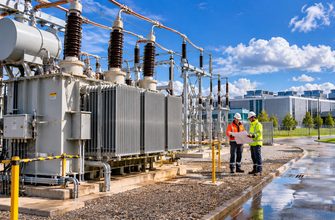
A pump can also lose its local supply without a site-wide blackout. A healthy reading upstream does not establish the state of every downstream circuit. Cooling power needs to be traced to the equipment that actually moves the heat.
Follow the heat beyond the server
Our explanation of where the heat from a 135 kW AI rack goes follows the full route from electronics to the outdoors. The same approach helps diagnose a cooling interruption.
A powered server still needs an open heat-removal path
IT electrical path: protected power → rack distribution → servers.
Cooling dependencies: equipment power, controls, airflow, liquid flow and outdoor heat rejection.
-
01 → Room air
The server releases heat
Fans carry heat from components into the room’s cooling airflow.
-
02 → Water loop
A cooling coil collects it
A computer room air handler moves warm air across a chilled-water coil.
-
03 → Cooling plant
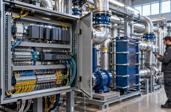
Pumps transport it
Circulating water carries the collected heat toward the chiller.
-
04 → Outdoors
The plant rejects it
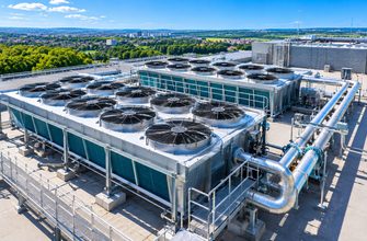
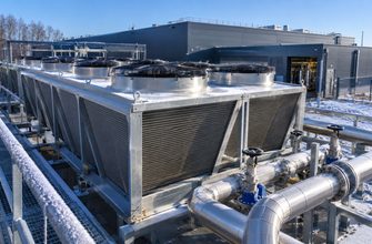
An air-cooled chiller transfers the heat to outside air.
The diagram separates collecting heat from rejecting it. Moving warm air around a room is not enough if the water coil cannot absorb that heat. Circulating water is not enough if the plant cannot cool it again.
Electricity can return before useful cooling does
Restored voltage is only part of recovery. Equipment may still be waiting for a start command, an allowed operating condition or its configured restart sequence.
For a concrete manufacturer example, the Liebert AFC installer/user guide, section 9.5, specifies different restart behavior for different refrigerant configurations and interruption lengths. Some conditions require a manual restart. Those rules belong to that product and configuration; they are not universal data-center timings.
A site can therefore have electrical supply available while part of its cooling plant remains stopped. The equipment’s actual state and alarm history explain more than a single green power indicator.
| Observed signal | What remains uncertain | Useful evidence |
|---|---|---|
| UPS output is healthy | Whether cooling equipment has its required supply. | Local power status for pumps, fans and controls. |
| A pump has a run command | Whether sufficient liquid is circulating. | Measured flow and pressure, alongside equipment feedback. |
| The chiller has power | Whether it has restarted and is delivering useful cooling. | Operating state, alarms and leaving-water temperature. |
| The room average looks normal | Whether individual rack inlets are getting warmer. | Local temperature trends at affected racks. |
An example: the electrical event ends, but the cooling interruption continues
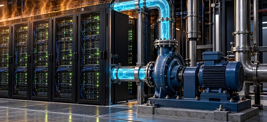
The servers stay online while a pump remains stopped
- A brief supply disturbance occurs. The IT UPS maintains power to the servers. A cooling pump on a different path stops.
- The supply recovers. In this scenario, the pump’s drive remains in a fault state awaiting the site’s approved recovery procedure.
- Heat transport falls. The air-handler fans continue moving air, but insufficient water flow limits what their coils can remove.
- Operators compare the right signals. Rack-inlet temperatures are rising. Pump feedback and measured flow reveal a problem that the IT power dashboard cannot show.
- Recovery is verified. After the facilities team resolves the fault under its operating procedure, it confirms restored flow and improving temperatures rather than relying on an alarm reset alone.
A hypothetical sequence, not a reported outage. Drive behavior, standby response and recovery procedures depend on the installation. No temperature-rise rate or safe waiting period is assumed.
Stored cold water helps only if the heat can reach it
A thermal reserve can bridge a chiller interruption. Vertiv’s chilled-water systems white paper explains how cold-water storage can supplement supply when chillers stop.
Its value depends on the usable stored cooling and a working delivery path. A tank does not replace the circulation needed to carry heat away from the load. Pump availability, flow and the way the reserve is connected remain part of the design.
This is also why liquid cooling for network equipment extends the thermal dependency beyond GPUs. Every connected load needs the relevant cooling path to remain available.
Test recovery as a complete sequence
Spare equipment is useful when the system can bring it into service under the conditions that actually occur. A recovery test should establish more than whether each component can start independently.
Schneider Electric’s Data Center Projects: Commissioning describes testing sequenced failures, restart and return to stable operation, both for components and for the integrated system. It also discusses using load banks when the installed IT load is insufficient for testing.
For the scenario in this article, the meaningful evidence is a coordinated record: electrical events, equipment states, flow and temperature trends. That record should show that cooling recovered while the load remained within its approved operating limits.
When the servers still have power but temperatures rise, follow the heat-removal path. Find which link stopped doing its job, then verify that the full path works again.