- The important points
- The critical part of a fiber connection is smaller than you think
- Two connector surfaces. One important difference.
- Clean optical interface
- Contaminated interface
- How a speck of dust becomes a network problem
- Why the link may stay online even when something is wrong
- Why a tiny optical fault matters to an AI workload
- Where one optical connection enters the computing path
- GPU server
- Network adapter
- Optical link
- Network fabric
- What engineers see when an optical link starts failing
- Link flaps
- BER and FEC
- Received power
- Fault location
- Why a counter alone isn’t enough
- How technicians determine whether a connector is actually contaminated
- A disciplined diagnostic sequence
- Why this becomes important in enormous AI data centers
- The experiment that could separate a dirty connector from a bad assumption
- What a controlled test would require
- The smallest fault can reveal the biggest computing dependency
- Sources and reporting notes
Imagine an AI training cluster where the GPUs are healthy, the servers have plenty of memory, and yet the job keeps slowing down. One network connection begins reporting errors. The hardware looks intact. Its cable is firmly plugged in.
The culprit could be something almost impossible to see: contamination on the end of an optical fiber.
This is not a hypothetical weakness invented for AI. NVIDIA’s DGX SuperPOD cabling documentation explicitly warns that dust on optical connections can degrade transmission. In the single-mode fiber described by NVIDIA, the light-carrying core is only about nine micrometers across.
Meanwhile, modern AI networks are moving enormous amounts of information between GPUs. Meta’s October 2026 IceCube announcement describes network switches with 128 ports rated at 800 gigabits per second each.
Faster networking makes the physical connections between machines worth investigating. How can microscopic dirt interfere with a high-speed link, what does that look like in network telemetry, and how do engineers tell a dirty connector from another problem?
The critical part of a fiber connection is smaller than you think
A fiber-optic cable carries information using light. The signal passes through a carefully manufactured glass fiber and into the receiver at the other end of the link.
At a detachable connection, precision mechanical components position the optical interfaces so that light can pass between them with an acceptably small amount of loss.
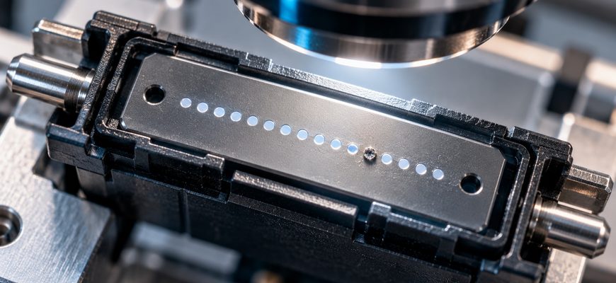
The outer connector housing may be large enough to hold comfortably. The critical optical region is much smaller.
NVIDIA uses this scale when describing the active optical area of single-mode fiber connections in its DGX SuperPOD cabling guidance. One micrometer is one-thousandth of a millimeter.
Not every fiber type has this exact core diameter. The figure is important here because it shows why an apparently insignificant contaminant can be relevant.
A small particle in the wrong place may interfere with the optical path or prevent ideal contact between connector surfaces.
Dirt on the outer housing does not have the same consequences as contamination in the optical contact region.
Two connector surfaces. One important difference.
Clean optical interface
The central optical region is unobstructed.
Inspection finds no significant contamination in the illustrated area.
Contaminated interface
A particle overlaps part of the optical region.
A poorly positioned particle may interfere with transmission or contact.
How a speck of dust becomes a network problem
Optical connections are engineered to keep insertion loss and unwanted reflections within acceptable limits.
Contamination can disturb that relationship. Depending on where it sits and what it is made of, a particle may block or scatter light, affect contact between connector surfaces or introduce additional reflections.
Rigid debris trapped during mating can also damage a surface. Cleaning can remove contamination, but cannot repair every scratch or chip.
The effect is not binary. Some contamination may have little measurable impact. A more serious obstruction may reduce the signal margin enough to produce errors, intermittent operation or a failed link.
Why the link may stay online even when something is wrong
Modern high-speed links can use forward error correction, or FEC, to recover from some transmission errors.
This means a link can appear operational while error-correction counters are increasing.
If the underlying signal becomes too poor, errors may exceed what the available correction mechanisms can handle. The result may involve dropped traffic or changes in link state.
There is an important distinction: an increasing FEC counter does not prove that dust caused the problem. Cabling, transceivers, electrical signal integrity, configuration and hardware faults can also affect link quality.
Why a tiny optical fault matters to an AI workload
A large AI training job spreads computation across many accelerators. Those devices often need to exchange data as the job progresses.
The network sits between one machine’s completed work and another machine’s ability to use that information.
A problem on an optical connection can therefore affect more than the network component itself.
The impact depends on the workload and the network’s redundancy. Some paths can be rerouted. Some errors can be corrected. Other failures may interrupt communication that a distributed job is waiting for.
Where one optical connection enters the computing path
GPU server
Produces information needed elsewhere in the cluster.
Network adapter
Sends and receives network traffic.
Optical link
Fiber connectors and transceivers carry optical signals.
Network fabric
Switches forward information toward other machines.
This is the hidden operational consequence. A GPU may be capable of working faster, but its distributed workload can be constrained by the communication surrounding it.
In our recent investigation of Meta’s liquid-cooled AI network rack , we looked at the enormous switching capacity required to connect modern accelerators.
The optical connector is a smaller part of that same system. A network’s advertised speed means less if the physical links cannot maintain adequate signal quality.
What engineers see when an optical link starts failing
A dirty fiber does not announce itself as a dirty fiber in the software.
Instead, engineers investigate symptoms. NVIDIA’s October 2026 ConnectX troubleshooting guidance identifies several categories worth collecting at both ends of an affected link.
Link flaps
The physical connection repeatedly transitions between up and down. This is a symptom, not a diagnosis.
BER and FEC
Bit-error and correction statistics may reveal a changing quality margin before an obvious outage.
Received power
Supported optical modules can expose signal-power measurements that help assess the optical path.
Fault location
A controlled replacement of cable, optic or port helps establish which component the problem follows.
These signals are used in network troubleshooting. Their availability, names and interpretation vary by network platform.
Why a counter alone isn’t enough
Suppose a switch reports increasing bit errors. That tells an operator something useful: the link deserves investigation.
But it does not identify the cause. There might be a defective optic, a problematic cable, incorrect settings or another physical issue.
NVIDIA recommends recording evidence from both ends of the connection and changing one suspect component at a time.
That approach prevents a common diagnostic mistake: replacing several parts at once, seeing the problem disappear and claiming to know which part was responsible.
How technicians determine whether a connector is actually contaminated
Optical-fiber inspection is a specialized task. The contact surface must be examined with appropriate optical inspection equipment rather than judged from the outside of the connector.
The IEC 61300-3-35:2022 standard covers visual inspection of fiber connector end faces, including debris, scratches and other defects.
The standard also makes an essential distinction: visual inspection does not replace optical performance testing, such as attenuation and return-loss measurements.
That means a connector should not be condemned solely because an image looks imperfect. Its actual performance matters.
Cisco’s fiber-maintenance documentation describes the same fundamental principle: inspect, clean when necessary, then inspect again.
The procedures must be matched to the connector and equipment. An unsuitable cleaning method can leave residue or create further damage.
Why this becomes important in enormous AI data centers
A small network might have only a limited number of optical connections. A large distributed computing environment can involve far more fiber terminations, transceivers and network ports.
Every additional physical connection is another item that must be installed, documented, monitored and maintained.
This does not mean a larger network is automatically unreliable. Redundant network designs can reduce the impact of individual failures.
But scale makes maintenance discipline consequential. Repeatable connector inspection and accurate port inventories matter because the network is too large to troubleshoot by intuition alone.
Optical connectivity also sits alongside other data-movement limits in AI systems. For example, PCIe bandwidth inside a local LLM system concerns transfers between different components of the same computer.
Fiber-optic networking instead helps carry information between machines. Both are reminders that data movement has physical costs and constraints.
The experiment that could separate a dirty connector from a bad assumption
The useful test is not to deliberately damage a production cluster or scatter contaminants onto operating connectors.
A controlled optical laboratory could instead compare documented connector conditions and actual performance measurements using an approved test setup.
The smallest fault can reveal the biggest computing dependency
AI infrastructure is often described through spectacular numbers: GPU counts, electrical power, memory capacity and network speed.
Yet those numbers describe systems that depend on ordinary physical engineering details. A connection still has to make contact. Light still has to reach the receiver with enough quality.
Dirt on a fiber connector will not automatically bring down an AI supercomputer. But a sufficiently poor connection can undermine one of the links that keeps its machines working together.
The lesson is not that advanced computing is fragile by definition. It is that reliable AI depends on measuring and maintaining the physical connections beneath the software.
Sources and reporting notes
This article is based on published technical documentation, an international standard and manufacturer engineering materials. No optical link or production AI cluster was independently tested by il.digital.
- NVIDIA — DGX SuperPOD: Maintaining NDR Connectors and Cables . Connector maintenance and single-mode optical-core scale.
- NVIDIA — ConnectX Physical Link, Cable, Optic, FEC and BER Triage . Updated October 8, 2026.
- IEC 61300-3-35:2022 — Visual Inspection of Fiber Optic Connectors and Transceivers . Published September 2022.
- Cisco — Inspection and Cleaning Procedures for Fiber-Optic Connections . Engineering maintenance guidance.
- Engineering at Meta — OCP Summit 2026: AI Networking Infrastructure . October 12, 2026.